Abstract
Over the last decade, hardware Trojans have gained increasing attention in academia, industry and by government agencies. In order to design reliable countermeasures, it is crucial to understand how hardware Trojans can be built in practice. This is an area that has received relatively scant treatment in the literature. In this contribution, we examine how particularly stealthy Trojans can be introduced to a given target circuit. The Trojans are triggered by violating the delays of very rare combinational logic paths. These are parametric Trojans, i.e., they do not require any additional logic and are purely based on subtle manipulations on the sub-transistor level to modify the parameters of the transistors. The Trojan insertion is based on a two-phase approach. In the first phase, a SAT-based algorithm identifies rarely sensitized paths in a combinational circuit. In the second phase, a genetic algorithm smartly distributes delays for each gate to minimize the number of faults caused by random vectors.
As a case study, we apply our method to a 32-bit multiplier circuit resulting in a stealthy Trojan multiplier. This Trojan multiplier only computes faulty outputs if specific combinations of input pairs are applied to the circuit. The multiplier can be used to realize bug attacks, introduced by Biham et al. In addition to the bug attacks proposed previously, we extend this concept for the specific fault model of the path delay Trojan multiplier and show how it can be used to attack ECDH key agreement protocols.
Our method is a general approach to path delay faults. It is a versatile tool for designing stealthy Trojans for a given circuit and is not restricted to multipliers and the bug attack.
The research was partially supported by NSF Grant CNS-1421352
You have full access to this open access chapter, Download conference paper PDF
Keywords
These keywords were added by machine and not by the authors. This process is experimental and the keywords may be updated as the learning algorithm improves.
1 Introduction
Hardware Trojans have gained increasing attention in academia, industry and government agencies over the last ten years or so. There is a large body of research concerned with various methods for detecting Trojans, cf., e.g., [14]. On the other hand, there is scant treatment in literature about how to design Trojans. Nevertheless, Trojan detection and design are closely related: in order to design effective detection mechanisms and countermeasures, we need an understanding of how Hardware Trojans can be built. This holds in particular with respect to Trojans that are specifically designed to avoid detection. The situation is akin to the interplay of cryptography and cryptanalysis.
There are several different ways that hardware Trojans can be inserted into an IC [14]. The insertion scenarios that have drawn the most attention in the past are hardware Trojans introduced during manufacturing by an untrusted semiconductor foundry. One of the main motivations behind this is the fact that the vast majority of ICs world wide are fabricated abroad, and a foundry can possibly be pressured by a government agency to maliciously manipulate the design. However, we note that a similar situation can exist in which the original IC designer is pressured by her own government to manipulate all or some of the ICs, e.g., those that are used in overseas products. Similarly, 3rd party IP cores are another possible insertion point.
The primary setting we consider is modification during manufacturing, but the method also carries over to the other scenarios mentioned above. The Trojan will be inserted by modifying a few gates at the sub-transistor level during manufacturing, so that their delay values increase. The goal is to select and chose the delays such that only for extremely rare input combinations these delays add up to a path delay fault. There are many possible ways to increase the delays in practice in stealthy ways. Since not a single transistor is removed or added to the design and the changes to the individual gates are minor, the Trojan is very difficult to detect post-manufacturing using reverse-engineering, visual inspection, side-channel profiling or most other known detection methods. Due to the extremely rare trigger conditions, it is also highly unlikely that the Trojan will be detected during functional testing. Even full reverse-engineering of the IC will not reveal the presence of the backdoor. Similarly, since the actual Trojan will be inserted in the last step of the design flow, the Trojan will not be present at higher abstraction levels such as the netlist. Accordingly, this type of Trojan is also very interesting for the scenario of stealthy, government-mandated backdoors. The number of engineers that are aware of the Trojan would be reduced to a minimum since even the designers of the Trojan-infested IP core would not be aware that such a backdoor has been inserted into the product. This can be crucial to eliminate the risk of whistle blowers revealing the backdoor. In summary, our method overcomes two major problems a Trojan designer faces, namely making the Trojan detection resistant and to provide a very rare trigger condition.
1.1 Related Work
The power of hardware Trojans was first demonstrated by King et al. in 2008 by showing how a Hardware Trojan inserted into a CPU can enable virtually unlimited access to the CPU by an external attacker [15]. The Trojan presented by King et al. was a Trojan inserted into the HDL code of the design. Similarly, Lin et al. presented a Hardware Trojan that stealthily leaks out the cryptographic key using a power side-channel [18]. This Hardware Trojan was also inserted at the netlist or HDL level, similarly to the Hardware Trojans that were designed as part of a student Hardware Trojan challenge at ICCD 2011 [19]. How to build stealthy Trojans at the layout-level was demonstrated in 2013 by Becker et al. which showed how a Hardware Trojan can be inserted into a cryptographically secure PRNG or a side-channel resistant SBox only by manipulating the dopant polarity of a few registers [4]. Another idea proposed in the literature is the idea of building Hardware Trojans that are triggered by aging [23]. Such Trojans are inactive after manufacturing and only become active after the IC has been in operation for a long time. Kumar et al. proposed a parametric Trojan [17] that triggers probabilistically with a probability that increases under reduced supply voltage.
Compared to research concerned with the design of Hardware Trojans, considerably more results exist related to different Hardware Trojan detection mechanisms and countermeasures. Most research focuses on detecting Hardware Trojans inserted during manufacturing. In many cases, a golden model is used that is supposed to be Trojan free to serve as a reference. One important question is how to get to a Trojan-free golden model. One approach proposed is to use visual reverse-engineering of a few chips to ensure that these chips were not manipulated. For this the layout is compared to SEM images of the chip. In [3] methods of how to automatically do this are discussed. Please note that not all Hardware Trojans are directly visibly in black-and-white SEM images. For example, to detect the dopant-level Hardware Trojans additional steps are needed, e.g., the method presented by Sugawara et al. [24]. One motivation of our work is that we might achieve an even higher degree of stealthiness by only slowing down transistors as opposed to completely changing transistors as has been done in [4]. Such parametric changes can be done cleverly to make visual reverse-engineering very difficult as discussed in Sect. 3. Another approach to Trojan detection uses power profiles that are used to compare the chip-under-test with previously recorded side-channel measurement of the golden chip. The most popular approach uses power side channels, first proposed by Agrawal et al. [2]. The idea to build specific Trojan detection circuitry has also been proposed, e.g., in [20]. However, these approaches usually suffer from the problem that a Trojan can also be inserted into such detection circuitry. Preventing Hardware Trojans inserted at the HDL level by third party IP cores has been discussed, e.g., in [13] and [26]. Efficient generation of test patterns for Hardware Trojans triggered by a rare input signals is the focus of work by Chakraborty et al. in [8] and Saha et al. in[21].
1.2 Our Contribution
The main contributions of this paper can be summarized as follows:
-
We introduce a new class of parametric hardware Trojans, the Path Delay Trojans. They posses the two desirable features that they are (i) very stealthy and thus difficult to detect with most standard methods and (ii) have very rare trigger conditions.
-
We present an automation flow for inserting the proposed style of Trojan. We propose an efficient, SAT solver-based path selection algorithm, which identifies suitably rare paths within a given target circuit. We also propose a second algorithm, based on genetic algorithms, for distributing the necessary delay along the rare path. The key requirement is to minimize the effect of the added delay on the remaining circuit.
-
As a case study for the effectiveness of the proposed method, a Trojan multiplier is designed. We were able to identify a rare path and perform specific delay modification in a 32-bit multiplier circuit model in such a way that the faulty behavior only occurs for very few combinations of two consecutive input values. We note that the input space of the multiplier is \((2^{32})^2 = 2^{64}\) so that most random input values occur very rarely during regular operation.
-
We show how the Trojan multiplier can used for realizing the bug attack by Biham et al. [5, 6] and propose a related attack on the ECDH key agreement protocol. We provide probabilities for this new bug attack variant. A precomputation phase reduces the attack complexity and makes the attacks practical for real-world scenarios. We show that the attacker can engineer the failure probability to the desired level by increasing the introduced propagation delay of the Trojan.
2 Overview of the Proposed Method
This work implements Trojan functionality in a given target circuit by using path delay faults (PDF), without modification to logic circuit, to induce inaccurate results for extremely rare inputs. Before describing the details of our method, we first define the notion of a viable delay-based Trojan in the unmodified HDL of the circuit as follows. A viable delay-based trojan must posses the following two properties.
-
Triggerability. For secret inputs, which are known to the attacker, cause an error with certainty or relatively high probability.
-
Stealthiness. For randomly chosen inputs, cause an error with extremely low probability.
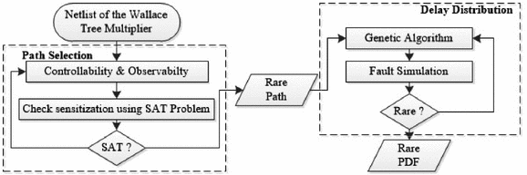
As shown in Fig. 1, our method of creating triggerable and stealthy delay-based Trojans consists of two phases: path selection and delay distribution. We give an overview of each phase here, and give detailed descriptions in Sect. 4.
Path Selection: The path selection phase finds a rarely sensitized path from the primary inputs of a combinational circuit to the primary outputs. The algorithm chooses the path incrementally by adding gates to extend a subpath backward toward inputs and forward toward outputs. The selection of which gates to include is guided by controllability and observability metrics so that the path will be rarely sensitized. To ensure that the selected path can be triggered, a SAT-based check is performed to ensure that the path remains sensitizable each time a gate is added. In addition to ensuring that the path is sensitizable, the SAT-based check also provides the Trojan designer with a specific input combination that will sensitize the path. This input combination will later serve as the trigger for the Trojan. Details of the path selection are given in Sect. 4.1.
Delay Distribution: After a rarely sensitized path is selected, the overall delay of the path must be increased so that a delay fault will occur when the path is sensitized; this is required for the Trojan to be triggerable. However, any delay added to gates on the selected path may also cause delay faults on intersecting paths, which would cause more frequent errors and compromise stealthiness. Our delay distribution heuristic addresses this problem by smartly choosing delays for each gate to minimize the number of faults caused by random vectors. At the same time, the approach ensures that the overall path delay is sufficient for the fault to occur when the trigger vectors are applied. Details of delay distribution are given in Sect. 4.2.
3 Delay Insertion
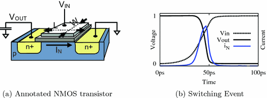
Delay faults occur when the total propagation delay along a sensitized circuit path exceeds the clock period. Our algorithm causes delay faults by increasing the delay of gates on a chosen path. While the approach is compatible with any mechanism for controlling gate delays, in this section we provide background on practical methods that a Trojan designer might use to implement slow gates. In static CMOS logic, a path delay fault is not triggered by a single input vector, but instead is triggered by a sequence of two input vectors applied on consecutive cycles. The physical reason for delay being caused by a pair of inputs is that delay depends on the charging or discharging of capacitances, and the initial states of these capacitances in the second vector are determined as final states from the first vector. Assuming the capacitances need to be charged or discharged along a path, as is the case in delay faults, the delay of each gate depends on how quickly it can charge or discharge some amount of capacitance on its output node, and diminishing the ability of a gate to do so will slow it down. There are several stealthy ways of changing a circuit to make gates slower. As an example, we list three methods below. We note that circuit designers typically face the opposite and considerably more difficult task, namely making gates fast. The ever-shrinking feature size of modern ICs is amenable to our goal of slowing gates down through minuscule alterations (Fig. 2).
-
Decrease Width. A gate library typically includes several drive strengths for each gate type, corresponding to different transistor widths. A narrow transistor is slower to charge a load capacitance because transistor current is linear in channel width. A straightforward way to increase delay is to replace a gate with a weaker variant of the same gate, or to create a custom cell variant with an extremely narrow channel. A limitation to using a downsized gate is that an attacker who delayers the chip could potentially observe the sizing optically, depending on how much the geometry has been altered.
-
Raise Threshold. A second way of increasing gate delay is to increase threshold voltages of selected transistors through doping or body biasing. Dual-Vt design is common in ICs and allows transistors to be designated as high or low threshold devices; low threshold devices are fast and used where delay is critical, and high threshold devices are slow and used elsewhere to reduce static power. Typically no more than two threshold levels are used on a single chip because creating multiple thresholds through doping requires additional process steps, but in principle an arbitrary number of thresholds can be created. Body biasing, changing the body-source voltage of MOSFETs, is another way to change threshold and delay [16]; specifically, a reverse body bias (i.e., body terminal at lower voltage than source) raises threshold voltage and slows down a device. Regardless whether the mechanism is doping or body biasing, a raised threshold voltage will cause transistors to turn on later when an input switches, and to conduct less current when turned on, so the output capacitance connected to the transistor will be charged or discharged more slowly. Both, changing to dopant concentrations and body biasing, are difficult to detect, even with invasive methods.
-
Increase Gate Length. Delay of chosen gates can be increased by gate length biasing. Lengthening the gate of transistor causes a reduction in current, and therefore increases delay [11]. Again, the likelihood of detection depends on the degree of the alteration.
We note that the methods sketched above (and other slow-down alterations) can be combined such that each manipulation is relatively minor and, thus, more difficult to detect.
4 Finding a Trojan Path
Fundamentally, the challenge in designing and validating triggerable and stealthy delay-based Trojans is that timing and logical sensitization cannot be decoupled. Regardless of the type of path sensitization considered, the probability of causing an error is not a well-defined concept until after delays are assigned. Therefore, when designing a candidate Trojan, path selection and delay assignment must both be considered. We will use a heuristic for this which combines logical path selection and delay distribution along a chosen path.
4.1 Phase I: Rare Path Selection
In this phase we try to select a path among huge number of paths existing in the netlist of a multiplier circuit, in such a way that random inputs will very rarely sensitize the path. The rareness is a first step towards ensuring stealthiness of the Trojan.
Controllability and Observability: Before giving our algorithm, we introduce several preliminaries. First, we note that every node in the circuit has a controllability metric and an observability metric associated with the 0 value and the 1 value. Controllability and observability are common metrics used in testing. Controllability of a 0 or 1 value on a circuit node is an estimate of the probability that a random input vector would induce that value on that node. Observability of a 0 or 1 value on a node is an estimate of the probability with which that value would propagate to some output signal when a random vector is applied. For rareness, we seek a path that includes low controllability nodes and low observability nodes, as this would indicate that the values on the path rarely occur randomly, and when they do occur they are usually masked from reaching the outputs. We estimate controllability using random simulation, and observability using random fault injection [12].
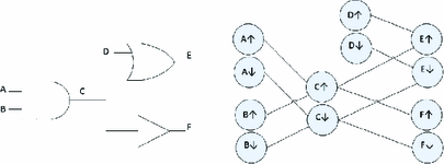
Timing Graph: The propagation delays of logic paths in combinational VLSI circuits are typically represented using weighted DAGs called timing graphs. Each node in a circuit will have two nodes in the timing graph, representing rising and falling transitions on the node; we use the terms transition and node interchangeably when discussing timing graphs. A directed edge between two nodes exists if the transition at the tail of the edge can logically propagate to the one at the head. The edges that exist in the timing graph therefore depend on the logic function of each gate in the circuit (see Fig. 3).
For example, an AND gate with inputs A and B, and output X, will have an edge from \(A\uparrow \) to \(X\uparrow \), from \(A\downarrow \) to \(X\downarrow \), from \(B\uparrow \) to \(X\uparrow \), and from \(B\downarrow \) to \(X\downarrow \), but will not have an edge from \(A\uparrow \) to \(X\downarrow \) because a rising transition on an AND gate input cannot induce a falling output. In timing analysis, e.g. STA, the edge weights of a timing graph represent propagation delay, but for our purpose of path selection, the delays are ignored and we utilize only the connectivity of the timing graph.
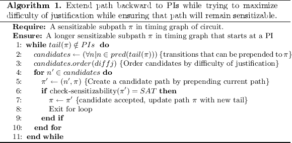
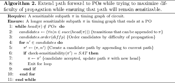
Selecting a Path Through Timing Graph: Our path selection technique seeks to find a path \(\pi \) through the timing graph of the circuit that is rarely sensitized. Note that the delays are not considered in this phase of the work. Path \(\pi \) is initialized to contain a single hard to sensitize transition somewhere in the middle of the circuit. More formally, the starting point for the path search is a rising or falling transition on a single node such that the product of its 0 and 1 controllability values is the lowest among all nodes in the circuit. This initial single-node path \(\pi \) is then extended incrementally backward until reaching the primary inputs (PIs), and extended incrementally forward until reaching the primary outputs (POs). The backward propagation is given in Algorithm 1, and the forward propagation is given in Algorithm 2.
First we explain the backward propagation heuristic in Algorithm 1. Starting from the first transition (i.e. the tail) on the current path \(\pi \), we repeatedly try to extend the path back toward the PIs by prepending one new transition to the path. To select such a transition, the algorithm creates a list of candidate transitions that can be be prepended to the path. In the timing graph, these candidates are predecessor nodes to the current tail of \(\pi \). The list of candidate nodes is then sorted according to diffj, the difficulty of creating the necessary conditions to justify the transition. See Table 3 in the appendix for the formula used to compute diffj for each transition on each gate type. Note that our difficulty metric is weighted to always prefer robust sensitization first, and only resort to non-robust sensitization when there are no robustly sensitizable nodes in the list of candidates. Whenever a node is prepended to \(\pi \) to create a candidate path \(\pi '\) (line 5) the sensitizability of \( \pi '\) is checked by calling check-sensitizability function. In this function SAT-based techniques [9] are used to check sensitizability of a path and to find a vector pair that justifies and propagates a transition along the path (line 6). If the SAT solver returns SAT, then path \(\pi '\) is known to be a subpath of a sensitizable path from PIs to POs. Because the candidates are visited in order of preference, there is no need to check other candidates after finding a first candidate that produces a sensitizable path. At this point, the algorithm updates \(\pi \) to be \(\pi '\) and the algorithm exits the for loop having extended the path by one node. If this newly added tail node is not a PI, then the algorithm will again try to extend it backwards.
The forward propagation algorithm (Algorithm 2) is similar to the aforementioned backward propagation algorithm, except that it adds nodes to the head of the path until reaching POs. At each step of the algorithm, a list of candidates is again formed. In this case, the candidates are successors of the head of the path (line 2) instead of predecessors of the tail, and they are ordered according to difficulty of propagation (line 3) instead of difficulty of justification (see Table 4 in Appendix A). Each time a new candidate path is created by adding a candidate node to the existing path, a sat check is again performed to ensure that the nodes are only added to \(\pi \) if it remains sensitizable (line 6).
4.2 Phase II: Delay Distribution
Once a path is selected, we must increase the delay of the path so that the total path delay will exceed the clock period and an error will occur when the path is sensitized. Yet, we must be careful in choosing where to add delay on the path, because the gates along the chosen path are also part of many other intersecting or overlapping paths. Any delay added to the chosen path therefore may cause errors even when the chosen path is not sensitized. To ensure stealthiness, we must minimize the probability of this by smartly deciding where to add delays along the path.
We use a genetic algorithm to decide the delay of each gate that will cause the Trojan to be stealthy. Genetic algorithm is an optimization technique that tries to minimize a cost function by creating a population of random solutions, and repeatedly selecting the best solutions in the population and combining and mutating them to create new solutions; the quality of each solution is evaluated according to a fitness function. We use the genetic algorithm function ga in Matlab [1], and do not utilize any special modifications to the genetic algorithm implementation. Our interaction with the ga function is limited to providing constraints that restrict the allowed solution space, and a fitness function for evaluating solutions. We describe these constraints and fitness function here.
Constraint on Total Path Delay. Given a chosen path \(\pi \) comprising gates \((p_0,p_1,\dots ,p_n)\) and assuming a target path delay of D, the genetic algorithm decides the delay of each gate on the path. Our first constraint therefore specifies that the sum of assigned delays along the path is equal to the target path delay D. To cause an error, D must exceed the clock period, and we later show advantages of using different values of D.
Constraint on Delay of Each Gate. Next we provide the genetic algorithm with a hint that helps it to discover reasonable delays for each gate. In this step, we use \(d'_i\) to represent the nominal delay of the \(i^{th}\) gate on chosen path \(\pi \), and \(s_i\) to represent the a slack metric associated with the same gate. Each slack parameter \(s_i\) describes how much delay can be added to the corresponding gate without causing the path to exceed the clock period. Because the targeted path delay D does exceed the clock period, gate delays are allowed to exceed their computed slack. The slack for each gate is computed as a function of the nominal delay of the gate, data dependency, and the clock period [10, 25]. The following equation shows the constraint on delay of gate i , where c is a constant.
Fitness Function. Simply stated, the cost function that we want to minimize is the probability of causing an error when random input vectors are applied to the circuit. Because there is no simple closed-form expression for this, we use random simulation to evaluate the cost of any delay assignment. When the genetic algorithm in Matlab needs to evaluate the cost of a particular delay assignment, it does so by executing a timing simulator. The timing simulator, in our case ModelSim, applies random vectors to the circuit-under-evaluation and a golden copy of the circuit and compares the respective outputs to count the number of errors that occur. These errors are caused by the delay assignments in the circuit-under-evaluation. The cost that is returned from the simulator is the percentage of inputs that caused an error for this delay assignment. As the genetic algorithm proceeds through more and more generations of solutions, the quality of the solutions improve. Matlab’s genetic algorithm implementation comes with a stopping criterion, so we simply allow the algorithm to run until completion.
5 Experimental Results
We now evaluate the effectiveness of our method of designing Trojans, using a \( 32 \times 32 \) Wallace tree multiplier as a test case. The circuit has a nominal critical path of length 128, and the delay of this path is 2520 ps.
5.1 Evaluation of Phase I (Path Selection)
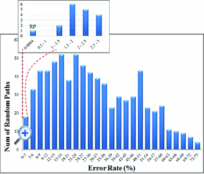
To evaluate the ability of our path selection algorithm (Sect. 4.1) to find a rare path, we compare the stealthiness of the path selected by the algorithm against the stealthiness of 750 randomly chosen paths. For each of these paths, we seek to find how often an error would occur under random inputs if the path delay is increased. We measure this by uniformly increasing the delay of each gate on the path such that the total delay of the path is 5040 ps, which is twice the delay of the nominal critical path. After the delay modification, 10,000 random vectors are applied and the number of error-causing vectors is counted. The histogram of Fig. 4 shows the result; the x-axis represents error rates, and the y-axis shows how many of the paths have each error rate. The result shows that a majority of paths would cause frequent errors if their delay is increased, and these paths are thus unsuitable for stealthy Trojans. The rare path (RP) selected by our algorithm caused an error for only 4 of 10,000 vectors. By comparison, the best of the random paths caused an error in 174 of 10,000 vectors. In this experiment, the path chosen by the path selection algorithm is 43x less likely to cause an error than the best of 750 random paths. Note that this experiment is conservative in that the amount of additional delay added is very large, and the delay is not smartly distributed along the path to minimize detection.
5.2 Evaluation of Phase II (Delay Distribution)
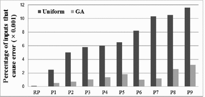
To evaluate the effectiveness of our delay distribution method, we apply the proposed method (Sect. 4.2) on 10 paths from the multiplier. These 10 paths are the rare path chosen by the path selection algorithm, and 9 paths randomly selected from the set of all paths that caused less than 10 % error rates in Fig. 4. For each of these paths, we use the genetic algorithm to optimally allocate a total delay of 3276 ps (i.e. 1.3 times of the delay of the nominal critical path) over the path, and then evaluate the error probability using random simulation with 5,000,000 vectors. Figure 5 shows the error probability of each path before and after applying our proposed delay distribution method. In each case, the optimization step reduces the probability of causing an error by at least 3.5x. For the rare path (RP), just one error in 5,000,000 vectors is caused after delay distribution. This result shows that, for a given total path delay, optimizing the delay assignment along the path can reduce the probability of having an error when random vectors are applied. It is important to note that this improvement in stealthiness comes from minimizing the side effects of the added delay, and does not impact triggerability when vectors are applied that actually sensitize the entire chosen path.
5.3 Overall Evaluation
We evaluate our overall methodology comprising path selection and delay distribution on the \(32\times 32\) Wallace Tree multiplier circuit. Instead of assuming a particular clock frequency, here we examine whether it is possible to add delay to the chosen rare path such that the circuit will (1) exceed the nominal critical path delay of 2520 ps when the applied input sensitizes the rare path, and (2) always have delay of less than 2520 ps otherwise. We first distribute delay uniformly over the path, and then apply the same total delay to the path but distribute it using the genetic algorithm (Sect. 4.2). The results are shown in Table 1. Despite simulating 260 million random vectors, we are unable to randomly discover any vectors in which the circuit delay exceeds 2520 ps. Yet, when applying a vector pair produced by our SAT-based sensitization check, we observe that the chosen path delay does exceed 2520 ps. As simulating 260 million vectors on a circuit this size already used more than 240 h of computation on an AMD Opteron (TM) Processor running at 2.3 GHz with 8 cores and 64 GB RAM, it will become quite expensive to check increasing numbers of vectors beyond 260 million. This highlights a significant challenge: given a space of \(2^{128}\) possible vector pairs that might cause an error, it is very hard to estimate the probability of an error that is sufficiently rare. If the probability of error is around or above roughly \(2^{-26}\), then random simulation will suffice to find a few errors and estimate the error probability. If the probability of error is below roughly \(2^{-98}\) it would be possible to use SAT to exhaustively enumerate all \(2^{30}\) vectors that would cause an error. Unfortunately, for very interesting region of error probabilities between \(2^{-26}\) and \(2^{-98}\) there is no clear solution for estimating the error probabilities.
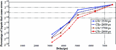
When the amount of delay added to the rare path is increased, and the probability of error grows above \(2^{-26}\), the error probability can feasibly be estimated with random simulation. In this regime, we can evaluate the tradeoff of delay and trigger probability. For example, when the chosen path is given a total delay of 3150 ps allocated using genetic algorithm for delay distribution, and the circuit is operated at a clock period of 2800 ps (as might be reasonable for a nominal critical path of 2520 ps) an erroneous output occurs with probability of roughly \(2^{-24}\) (once every 16 million multiplications) when random inputs are applied. The overall tradeoff is shown in Fig. 6 for different clock periods. One can exploit this tradeoff to create a desired error probability by increasing or decreasing the total amount of delay added to the chosen path.
6 Bug Attack on ECDH with a Trojan Multiplier
The main motivation of choosing a multiplier as our case study is the bug attack paper by Biham et al. [5, 6]. They showed how several public key implementations can be attacked if the used multiplier computes a faulty response for some rare inputs. The real-world implications of bug attacks were first demonstrated by Brumley et al. in 2012 when they showed how a software bug in an implementation of the reduction step of an elliptic curve group operation in OpenSSL could be exploited to recover private ECDH-TLS server keys [7]. Note that while they exploited a software bug as opposed to a hardware bug and a modular reduction as opposed to a multiplication, the attack idea itself is the same as in the original bug attack paper [5].
6.1 Fault Model of the Trojan Multiplier
The Trojan Multiplier introduced in the precious Section has a different fault model than the one assumed in [5]. In particular, the output of the Trojan Multiplier does not only depend on the current input but also on the previous inputs, i.e., it has a state. We define the multiplication of two 32-bit numbers \(a_1\), \(b_1\) with our Trojan Multiplier as \(\tilde{y}=MUL_{a_0,b_0}(a_1,b_1)\) where \(a_0,b_0\) is the previous input pair to the multiplier. The list F of quadruples \((a_0,b_0,a_1,b_1)\) are all input sequences for which the Trojan Multiplier computes a faulty response:
Outputs computed with the Trojan Multiplier are always represented with a tilde. An ECC scalar multiplication of point \(Q\in E\) with an integer k is denoted as \(R= k \cdot Q\). An elliptic curve scalar multiplication using the Trojan Multiplier is denoted with an \(\odot \), i.e., \(\tilde{R}= k \odot Q\). In the following we assume that an attacker has knowledge of the Trojan Multiplier or access to a chip with the Trojan Multiplier such that the attacker knows for which inputs \(\tilde{R}\ne R\).
The attack complexity strongly depends on the probability that a multiplication results in a faulty response. In order to be able to compute this probability we make following definitions:
-
1.
\(P_{M(a_1,b_1)}\): Probability that for two random 32-bit integers \(a_1,b_1\) there exits at least one pair of 32-bit integers \(a_0,b_0\) such that \(\tilde{y}=MUL_{a_0,b_0}(a_1,b_1)\) computes a faulty response
-
2.
\(P_{M(a_1)}\): Probability that for a random 32-bit integers \(a_1\) there exits at least one triplet of 32-bit integers \(a_0,b_0,b_1\) such that \(\tilde{y}=MUL_{a_0,b_0}(a_1,b_1)\) computes a faulty response. Probability \(P_{M(b_1)}\) is defined in the same fashion.
-
3.
\(P_{M(a_0,b_0|a_1,b_1)}\): Probability that for two random 32-bit integers \(a_0,b_0\) and two given integers \(a_1,b_1\) the multiplication \(\tilde{y}=MUL_{a_0,b_0}(a_1,b_1)\) computes a faulty response if there exists at least one other input pair \(a'_0,b'_0\) for which \(\tilde{y}=MUL_{a'_0,b'_0}(a_1,b_1)\) computes a faulty response
-
4.
\(P_{M(a_0|a_1,b_1=b_0)}\): Probability that for a random 32-bit integers \(a_0\), and two given integers \(a_1,b_1\) the multiplication \(\tilde{y}=MUL_{a_0,b_0}(a_1,b_1)\) with \(b_0=b_1\) computes a faulty response if there exists at least one other input pair \(a'_0,b'_0\) for which \(\tilde{y}=MUL_{a'_0,b'_0}(a_1,b_1)\) computes a faulty response
Furthermore, we make following assumptions regarding these probabilities for the Trojan Multiplier :
-
1.
\(P_{M(a_1)}\approx P_{M(b_1)}\) and \(P_{M(a_1,b_1)}=P_{M(a_1)}\cdot P_{M(b_1)}\)
-
2.
\(P_{M(a_0,b_0|a_1,b_1)} \approx 0.09\)
-
3.
\(P_{M(a_0|a_1,b_1=b_0)} \approx 0.18\)
Assumption (1) follows from the fact that both inputs have the same impact on the propagation path of the signal. Hence it is reasonable that both values are equally important to determine if a multiplication fails. Assumption (2) is based on experimental results in which 892 out of 10,000 multiplication failed when \(a_0\) and \(b_0\) are changed randomly while keeping \(a_1\), \(b_1\) constant. Assumption (3) is based on a similar experiment in which 1813 out of 10,000 multiplication failed when \(a_0\) was changed randomly and \(b_0\) was fixed to \(b_0=b_1\) and \(a_1\) was kept constant as well.
6.2 Case Study: An ECDH Implementation with Montgomery Ladder
For our case study we assume a 255-bit ECDH key agreement with a static public key. Furthermore, we assume the implementation uses the Montgomery Ladder scalar multiplication. The ECDH key agreement works as follows: Given are a standardized public curve E (e.g. Curve25519) and the point \(G\in E\). The private key of the server is a 255 bit integer \(k_s\) and the corresponding public key is \(Q_s=k_s \cdot G\). The key agreement is started by the client by choosing a random 255-bit integer \(k_c\) and computing \(Q_c=k_c \cdot G\). The client sends \(Q_c\) to the server and computes the shared key \(R=k_s \cdot Q_s\). The server computes the shared secret key R using \(Q_c\) and his secret key \(k_s\) by computing \(R=k_S \cdot Q_c\). Usually, the key agreement is followed by a handshake to ensure that both the client and the server are now in possession of the same shared session key R.
The general idea of the bug attack is that the attacker makes a key guess of the first l bits of the secret key \(K_s\). Then the attacker searches for a point \(Q=m\cdot G\) such that the scalar multiplication \(\tilde{R}= k_s \odot Q\) results in a failure if, and only if, the most significant bits of \(k_s\) are indeed the l bits the attacker guessed. The attacker then sends Q to the server and completes the ECDH key exchange protocol by making a handshake with the shared key \(R=m\cdot Q_s\). If this handshake fails, the expected multiplication error in the Trojan Multiplier has occurred and hence, the attacker knows that his key guess is correct. This way more and more bits of the key are recovered consecutively. In the Montgomery Ladder scalar multiplication only one bit of the key is processed in each ladder step and the attack works as follows:
-
1.
Input: Elliptic curve E with point \(G \in E\) and public server key \(Q_s \in E\)
-
2.
Initialization: Set \(k=1_{(2)}\)
-
3.
Repeat for key bit 2 to 255:
-
(a)
Define \(k_0=k||0_{({2})}\) [Append a zero to the key k]
-
(b)
Define \(k_1=k||1_{({2})}\) [Append a one to the key k]
-
(c)
Repeatedly choose a value m and compute \(Q=m\cdot G\) until:
\((\tilde{P_i}= k_i \odot Q) \ne (P_i= k_i \cdot Q\)) for \(i\in \{0,1\}\)
\((\tilde{P_j}= k_j \odot Q) = (P_j= k_j \cdot Q\)) for \(j\ne i\), \(j\in \{0,1\}\)
-
(d)
Send Q to the server and complete handshake with \(R=m\cdot Q_s\)
-
(e)
If handshake failed, set \(k=k_i\), else set \(k=k_j\)
-
(a)
The attack described above is a straight forward adaption of the bug attack from [7]. However, in the Trojan multiplier scenario the attack can be improved significantly by adding a precomputation step. The main idea is to not use randomly generated points Q in step 3.c) but to use points Q in which the x-coordinate \(Q_x\) contains a \(b_1\) for which the Trojan Multiplier \(\tilde{y}=MUL_{a_0,b_0}(a_1,b_1)\) has a high chance to return a faulty response. That is, \(b_1\) is one of the inputs for which the Trojan Multiplier fails. In each step of the Montgomery Ladder algorithm the projective coordinate \(Z_2\) is computed with \(Z_2\leftarrow Z_2 \cdot Q_x\) Footnote 1 Hence, \(Q_x\), and therefore also \(b_1\), is used in every ladder step. Furthermore, the value \(Z_2\) is different depending on the currently processed key bit. Our improved attack targets this 255-bit integer multiplication \(Z_2 \cdot Q_x\) to find a Q such that \((\tilde{P_i} \ne P_i)\) while \((\tilde{P_j} \ne P_j)\) as needed in step 3.c) of the attack algorithm.
Unfortunately, the attacker cannot freely choose Q since the attacker needs to know m such that \(Q=m\cdot G\) to finish the handshake. Instead of computing suitable points for each attack, we propose to search for t suitable points Q during a precomputation step as described below:
-
1.
Input: Elliptic curve E with point \(G \in E\)
-
2.
Initialization: \(m=1\), \(Q=G\)
-
3.
Repeat t times:
-
(a)
\(m=m+1\), \(Q=Q+G\)
-
(b)
If \(Q_x\) contains \(b_1\), store m and Q in list L
-
(a)
To compute the probability that the 255-bit integer multiplication \(Z_2 \cdot Q_x\) fails the used multiplication algorithm is important. We assume that the schoolbook multiplication is used. One 255-bit schoolbook multiplication consists of 64 multiplications of which 8 have \(b_1\) as an operand. Since one of these multiplication is a 31-bit multiplication and we assume that only 32-bit multiplications can trigger the Trojan, 7 32-bit multiplications with \(b_1\) that can trigger the Trojan are performed in each ladder step. Furthermore, due to the FOR loops in the schoolbook multiplication, in 6 of these 7 multiplications \(b_0=b_1\), i.e., the second operand in the multiplication remains unchanged. Note that \(P_{M(a_0|a_1,b_1=b_0)} \approx 0.18\) and hence this is actually not a problem but rather helpful. The average number \(A_Q\) of points Q that need to be tested until a failure occurs for key bit 1 or 0 is therefore:
Let us assume that the attacker tries to find a point Q for key bit i. Since the attacker searches for a fault in the last Montgomery Ladder step, for every point Q the attacker needs to compute \(i-2\) Montgomery Ladder steps (for the first key bit no step is needed) and then two Montgomery Ladder steps for key bit 1 and 0 respectively to check if the multiplication fails. Hence, in total the attacker needs an average of \(A_M\) Montgomery Ladder steps to recover a 255 bit key:
To compute t points Q during the precomputation such that \(b_1\) is in \(Q_x\) the attacker needs in average
point additions. We chose \(t=16 \cdot A_Q\) which results in a failure probability of ca. \(3.3\cdot 10^{-8}\) which should be small enough for all reasonable attack scenarios. Table 2 summarizes the attack complexity for our improved bug attack with precomputation for different parameters for the Trojan Multiplier. To put these numbers into perspective, the hardware implementation of curve25519 presented in [22] can compute roughly \(2^{39.3}\) Montgomery Ladder steps per second on a Xilinx Zynq 7020 FPGA. Hence, especially for a failure probability of \(P_{M(a_1,b_1)}=2^{-48}\) the attack complexity of \(2^{39}\) Montgomery ladder steps (and \(2^{50}\) point additions that only need to be done once) is quite practical in a real-world scenario. On the other hand, the probability that the Trojan is triggered unintentionally during normal operation is about \(2^{-37}\) which is low enough to not cause problems (see Appendix B for details).
7 Conclusion
This paper introduced a new type of parametric hardware Trojans based on rarely-sensitized path delay faults. While hardware Trojans using parametric changes (i.e. that only modify the performance/parameters of gates) have been proposed before, the previously proposed parametric hardware Trojans cannot be triggered deterministically. They are instead either triggered after time by aging [23], triggered randomly under reduced voltage [17] or are always on and can leak keys using a power side-channel [4]. In contrast, the proposed parametric hardware Trojan in this paper can be triggered by applying specific input sequences to the circuit. Hence, this paper introduces the first trigger-based hardware Trojan that is realized solely by small and stealthy parametric changes. To achieve this, a SAT-based algorithm is presented which efficiently searches a combinational circuit for paths that are extremely rarely sensitized. A genetic algorithm is then used to distribute delays over all the gates on the path so that a path delay fault occurs when trigger inputs are applied, while for other inputs the timing criteria are met. In this way, a faulty response is computed only for a very small subset of input combinations.
To demonstrate the usefulness of the proposed technique, a 32-bit multiplier is modified so that, for some multiplications, faulty responses are computed. These faults can be so rare that they do not interfere with normal operations but can still be used by the Trojan designer for a bug attack against public key algorithms. As a motivating example, we showed how this can be achieved for ECDH implementations. Please note that while we used a multiplier as our case study, the general idea of path delay Trojans and the tool-flow and algorithms presented in this paper are not restricted to multipliers. Hence, this work shows that by only making extremely stealthy parametric changes to a design, a malicious factory could insert backdoors to leak out secret keys.
Notes
- 1.
See Appendix B of the IACR ePrint version for the Montgomery Ladder algorithm.
References
Genetic Algorithm. http://www.mathworks.com/discovery/genetic-algorithm.html. Accessed 01 Feb 2016
Agrawal, D., Baktir, S., Karakoyunlu, D., Rohatgi, P., Sunar, B.: Trojan detection using IC fingerprinting. In: IEEE Symposium on Security and Privacy (SP 2007), pp. 296–310 (2007)
Bao, C., Forte, D., Srivastava, A.: On reverse engineering-based hardware Trojan detection. IEEE Trans. Comput.-Aided Des. Integr. Circ. Syst. 35(1), 49–57 (2016)
Becker, G.T., Regazzoni, F., Paar, C., Burleson, W.P.: Stealthy dopant-level hardware Trojans. In: Bertoni, G., Coron, J.-S. (eds.) CHES 2013. LNCS, vol. 8086, pp. 197–214. Springer, Heidelberg (2013)
Biham, E., Carmeli, Y., Shamir, A.: Bug attacks. In: Wagner, D. (ed.) CRYPTO 2008. LNCS, vol. 5157, pp. 221–240. Springer, Heidelberg (2008)
Biham, E., Carmeli, Y., Shamir, A.: Bug attacks. J. Cryptology 1–31 (2015). http://dx.doi.org/10.1007/s00145-015-9209-1
Brumley, B.B., Barbosa, M., Page, D., Vercauteren, F.: Practical realisation and elimination of an ECC-related software bug attack. In: Dunkelman, O. (ed.) CT-RSA 2012. LNCS, vol. 7178, pp. 171–186. Springer, Heidelberg (2012)
Chakraborty, R.S., Wolff, F., Paul, S., Papachristou, C., Bhunia, S.: MERO: a statistical approach for hardware Trojan detection. In: Clavier, C., Gaj, K. (eds.) CHES 2009. LNCS, vol. 5747, pp. 396–410. Springer, Heidelberg (2009)
Eggersgl, S., Wille, R., Drechsler, R.: Improved SAT-based ATPG: more constraints, better compaction. In: IEEE/ACM International Conference on Computer-Aided Design (ICCAD), pp. 85–90 (2013)
Ghandali, S., Alizadeh, B., Navabi, Z.: Low power scheduling in high-level synthesis using dual-Vth library. In: 16th International Symposium on Quality Electronic Design (ISQED), pp. 507–511 (2015)
Gupta, P., Kahng, A.B., Sharma, P., Sylvester, D.: Gate-length biasing for runtime-leakage control. IEEE Trans. Comput.-Aided Des. Integr. Circ. Syst. 25(8), 1475–1485 (2006)
Heragu, K., Agrawal, V., Bushnell, M.: FACTS: fault coverage estimation by test vector sampling. In: Proceedings of IEEE VLSI Test Symposium, pp. 266–271 (1994)
Hicks, M., Finnicum, M., King, S.T., Martin, M.M., Smith, J.M.: Overcoming an untrusted computing base: detecting and removing malicious hardware automatically. In: IEEE Symposium on Security and Privacy (SP 2010), pp. 159–172 (2010)
Karri, R., Rajendran, J., Rosenfeld, K., Tehranipoor, M.: Trustworthy hardware: identifying and classifying hardware Trojans. Computer 10, 39–46 (2010)
King, S.T., Tucek, J., Cozzie, A., Grier, C., Jiang, W., Zhou, Y.: Designing and implementing malicious hardware. In: Proceedings of the 1st USENIX Workshop on Large-scale Exploits and Emergent Threats (LEET 08), pp. 1–8 (2008)
Kulkarni, S.H., Sylvester, D.M., Blaauw, D.T.: Design-time optimization of post-silicon tuned circuits using adaptive body bias. IEEE Trans. Comput. Aided Des. Integr. Circ. Syst. 27(3), 481–494 (2008)
Kumar, R., Jovanovic, P., Burleson, W., Polian, I.: Parametric Trojans for fault-injection attacks on cryptographic hardware. In: 2014 Workshop on Fault Diagnosis and Tolerance in Cryptography (FDTC), pp. 18–28. IEEE (2014)
Lin, L., Kasper, M., Güneysu, T., Paar, C., Burleson, W.: Trojan side-channels: lightweight hardware Trojans through side-channel engineering. In: Clavier, C., Gaj, K. (eds.) CHES 2009. LNCS, vol. 5747, pp. 382–395. Springer, Heidelberg (2009)
Rajendran, J., Jyothi, V., Karri, R.: Blue team red team approach to hardware trust assessment. In: IEEE 29th International Conference on Computer Design (ICCD 2011), pp. 285–288, October 2011
Rajendran, J., Jyothi, V., Sinanoglu, O., Karri, R.: Design and analysis of ring oscillator based design-for-trust technique. In: 29th IEEE VLSI Test Symposium (VTS 2011), pp. 105–110 (2011)
Saha, S., Chakraborty, R.S., Nuthakki, S.S., Mukhopadhyay, D.: Improved test pattern generation for hardware Trojan detection using genetic algorithm and Boolean satisfiability. In: Güneysu, T., Handschuh, H. (eds.) CHES 2015. LNCS, vol. 9293, pp. 577–596. Springer, Heidelberg (2015)
Sasdrich, P., Güneysu, T.: Implementing Curve25519 for side-channel-protected elliptic curve cryptography. ACM Trans. Reconfigurable Technol. Syst. (TRETS) 9(1), 3 (2015)
Shiyanovskii, Y., Wolff, F., Rajendran, A., Papachristou, C., Weyer, D., Clay, W.: Process reliability based Trojans through NBTI and HCI effects. In: NASA/ESA Conference on Adaptive Hardware and Systems (AHS 2010), pp. 215–222 (2010)
Sugawara, T., Suzuki, D., Fujii, R., Tawa, S., Hori, R., Shiozaki, M., Fujino, T.: Reversing stealthy dopant-level circuits. In: Batina, L., Robshaw, M. (eds.) CHES 2014. LNCS, vol. 8731, pp. 112–126. Springer, Heidelberg (2014)
Tang, X., Zhou, H., Banerjee, P.: Leakage power optimization with dual-Vth library in high-level synthesis. In: 42nd Annual Design Automation Conference (DAC 2005), pp. 202–207 (2005)
Waksman, A., Sethumadhavan, S.: Silencing hardware backdoors. In: IEEE Symposium on Security and Privacy (SP 2011), pp. 49–63 (2011)
Author information
Authors and Affiliations
Corresponding author
Editor information
Editors and Affiliations
Appendices
A Difficulty of Justification and Propagation Tables
B Montgomery Ladder
To be able to compute the exact attack complexity the details of the Montgomery Ladder are important to determine how many manipulations are performed in each step. Algorithms 3 and 4 describe the details of the assumed Montgomery Ladder implementation.
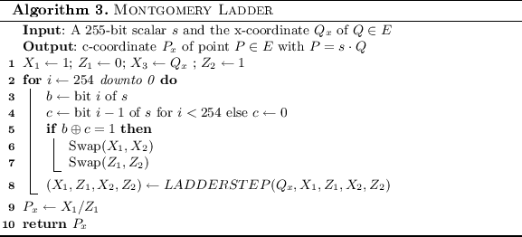
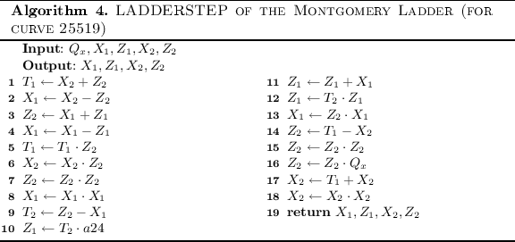
Computing the Failure Probability of a Scalar Multiplication. In this subsection we describe how the failure probability of a Montgomery Ladder scalar multiplication with schoolbook multiplication on the Trojan Multiplier can be compute. To compute the probability that the computation fails we fist compute the probability that a computation does not fail. As noted previously, in a 255-bit schoolbook integer multiplications with 32-bit word size, 64 multiplications are performed. From this 64 multiplications, 49 multiplications are the multiplications of two 32-bit numbers, while 6 are 32-bit times 31-bit multiplications and one 31-bit times 31-bit multiplications. We again assume that only 32-bit multiplications can result in a faulty response. In 42 multiplications the second operand is the same as in the previous multiplications and hence the probability that such a multiplication fails is:
For 7 multiplications the failure probability is:
The probability that no failure occurs during one Montgomery Ladder step is therefore:
A 255-bit scalar multiplication requires 254 Montgomery Ladder steps. Hence the probability that a failure occurs is given by:
Rights and permissions
Copyright information
© 2016 International Association for Cryptologic Research
About this paper
Cite this paper
Ghandali, S., Becker, G.T., Holcomb, D., Paar, C. (2016). A Design Methodology for Stealthy Parametric Trojans and Its Application to Bug Attacks. In: Gierlichs, B., Poschmann, A. (eds) Cryptographic Hardware and Embedded Systems – CHES 2016. CHES 2016. Lecture Notes in Computer Science(), vol 9813. Springer, Berlin, Heidelberg. https://doi.org/10.1007/978-3-662-53140-2_30
Download citation
DOI: https://doi.org/10.1007/978-3-662-53140-2_30
Published:
Publisher Name: Springer, Berlin, Heidelberg
Print ISBN: 978-3-662-53139-6
Online ISBN: 978-3-662-53140-2
eBook Packages: Computer ScienceComputer Science (R0)


